| W36CB1 | W36CB2 |
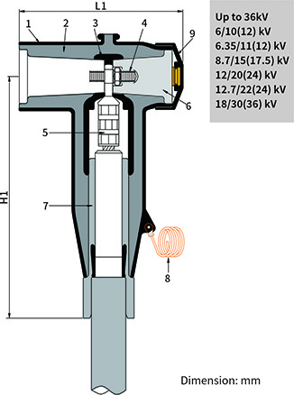
| L1(mm) | 197±3 | 200±3 |
| H1(mm) | 245±5 | 300±5 |
Design
1. External Screen
Moulded EPDM conductive rubber to ensure the connector touchable
2. Insulation
Moulded EPDM insulating rubber to ensure excellent electrical properties
3. Internal Screen
Moulded EPDM conductive rubber to control electrical stress
4. Two-headed Screw
To secure the conductor lug onto the bushing
5. Conductor Lug
To connect the cable conductor and bushing
6. Insulated Plug
Moulded epoxy plug having a metal insert to thread to accept the two-headed screw
7. Cable Adapter
To provide initial stress relief and watertight seal
8. Earthing Wire
To earth the external screen for the connector
9. End Cap
Moulded EPDM conductive rubber to protect against dust
Ordering instruction
The ordering formula as followed:
Step 1
Choose the highest system voltage: 36kV
Step 2
Select the connector body size and insulation range code from Table D that fits the diameter over cable insulation
Step 3
Select the conductor code from Table C for the conductor size and type
Step 4
Select the package. 1: 1pc/kit; 3: 3pcs/kit.
Table D
Connector body size and insulation range code
Connector Body Size | Insulation Range Code (For Cable adaptor) | Applicable Diameter over cable insulationφ(mm) |
| Min. | Max. |
| 1 | A | 20
| 23 |
| B | 23 | 25 |
| C | 25 | 28.5 |
| D | 28 | 31.5 |
| E | 31 | 35 |
| F | 34 | 37 |
| G | 36.5 | 39.5 |
| H | 39 | 42.5 |
2
| I | 36.5 | 40 |
| J | 39.5 | 43 |
| K | 43 | 47.5 |
| L | 47.5 | 49.5 |
Table C
Conductor Code
Conductor Cross-section (mm2) | Lug Code |
Copper Lug Code (Hexagonal compression)
| Connector Body Size*
| Aluminum Lug Code(Mechanical Bolted) | Connector Body Size* |
| 35 | 02C | 1
| M1 (AULZ25-95-16) | - | - | 1
|
| 50 | 03C | - | - |
| 70 | 04C | M2 (AULZ70-240-16) | - |
| 95 | 05C | - |
| 120 | 06C | - | - |
| 150 | 07C | - | - |
| 185 | 08C | - | - |
| 240 | 09C | - | - |
| 300 | 10C | - | - | M4 (AULZ300-630-16) | 2
|
| 400 | 11C | - | - |
| 500 | 12C | 2
| - | - |
| 630 | 13C | - | - |
Ordering example:
The cable is 36kV, 3*95mm2 aluminum conductor with core insulation diameter of 29mm. Order W36CB1DM13.
Note:
Sealing or solderless grounding kits shall be ordered separately.
Please add "-X" for cable with copper wire shield without armour, like W36CB1D05C3-X.
Feel free to contact us for detailed information.
*Please make sure the lug code mates with the connector body size if you need to repack the connector kits.


